Hypersonic Reentry Modeling
In this post, we discussing modeling for the hypersonic reentry problem. We give background details for the model used in this paper. (Mceowen, S., Calderone, D.J. , Tiwary, A., Zhou, J., Kim, T., Elango, P., Ackimese, B., Auto-tuned Primal-dual Successive Convexification for Hypersonic Reentry Guidance (submitted JGCD 2025))
Problem OverviewWe consider the following trajectory optimization problem $$ \begin{aligned} \min_{z,u} \ \ J(z) = v(t_f) \\ \text{s.t.} \ \ \dot{z} = f(z,u) \\ C(z,u) \leq 0 \\ g(z,u) \leq 0 \\ z(t_0) - z_0 = 0 \\ z(t_f) - z_f = 0 \end{aligned} $$ with state vector \(z\), control vector \(u\) control constraints \(C(z,u) \leq 0\) and path/state constraints \(g(z,u) \leq 0\). We detail each of these elements in the following sections.
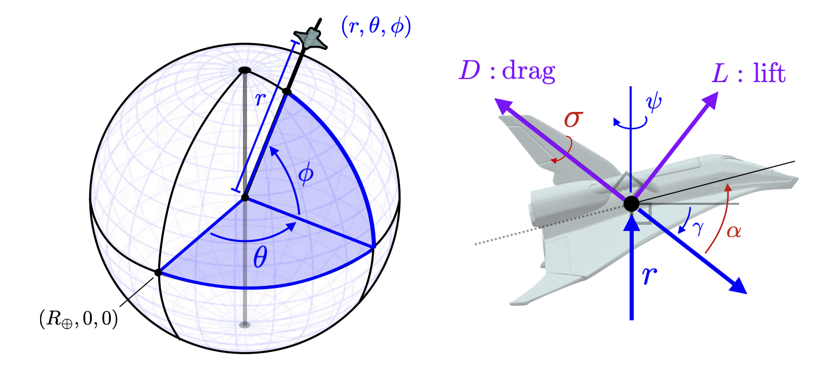
StatesThe state vector \(z\) consists of a polar coordinate representation of the location of the vehicle as well as orientation and velocity of the vehicle. We take \(z = (r,\theta_\phi,v,\gamma,\psi) \in \mathbb{R}^{6}\). \(r\in \mathbb{R}\) is the radial distance of the craft from the center of the earth. (\(R_\oplus \) is the surface radius of the earth and thus \(r \geq R_\oplus\) at all times.) \((\theta,\phi) \in [0,2\pi] \times [-\pi/2,\pi/2] \) are the longitude and latitude coordinates. We illustrate these coordinates in the left figure below.
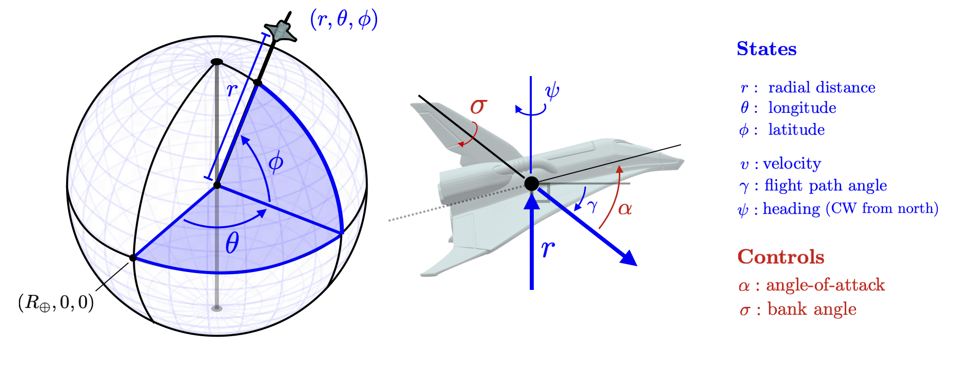
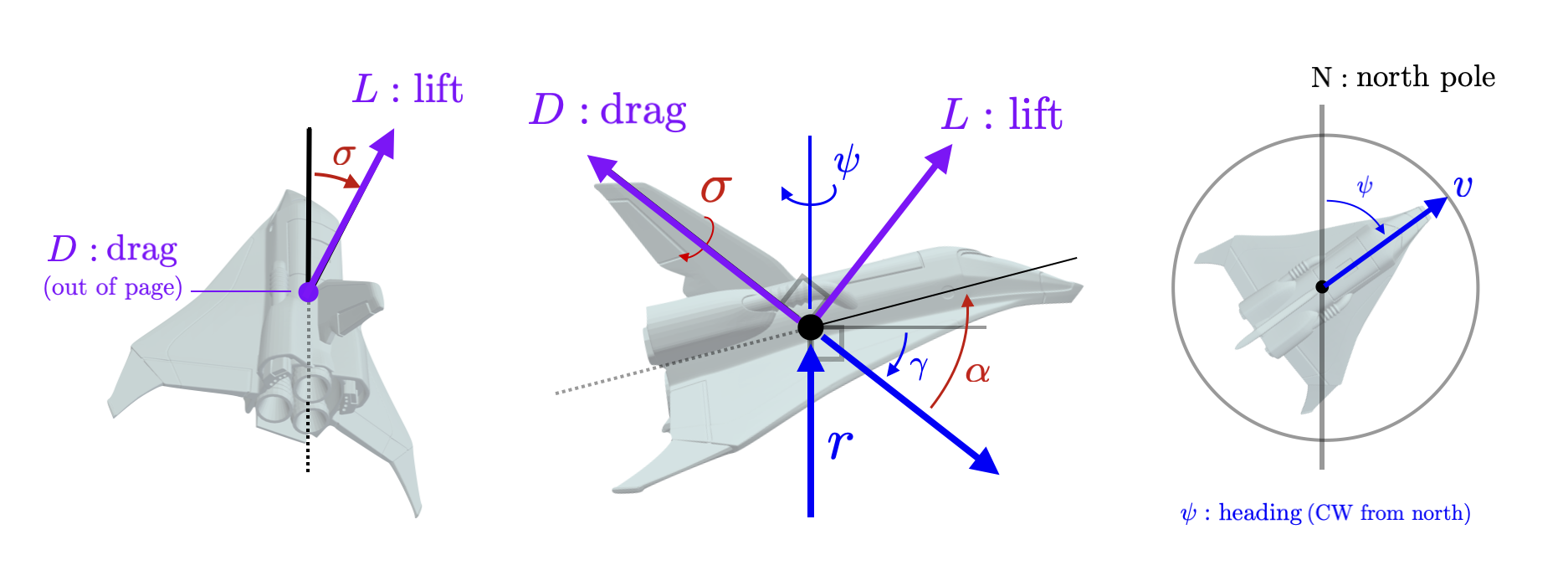
The flight path of the vehicle is measured by an angle \(\gamma \in [-\pi/2,\pi/2]\) measured down from horizontal. The velocity magnitude (in the direction of the flight path) is denoted by \(v \in \mathbb{R}\). The yaw orientation is given by \(\psi \in [-\pi,\pi]\) measured from orientation toward the north pole. These states are illustrated in the right figure above as well as the detailed figures here.
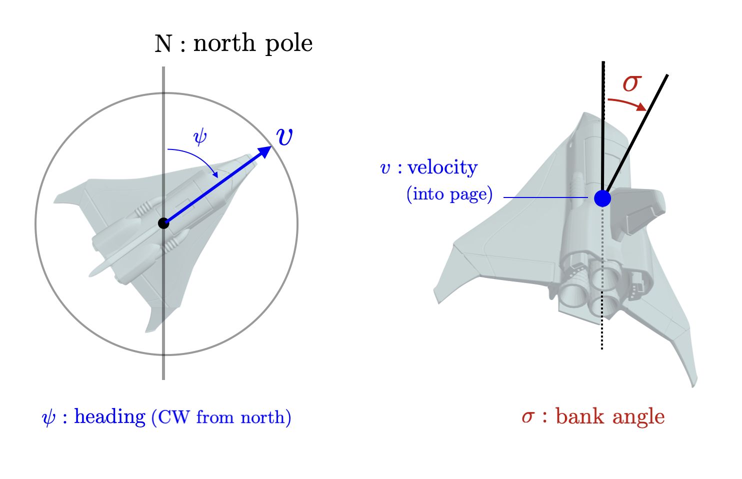
The control inputs for the vehicle are the angle-of-attack \(\alpha \in [-\pi,\pi]\) measured up from the flight path direction and the bank angle \(\sigma \in [-\pi/2,\pi/2]\) measured around the flight path vector as illustrated in the images above. Note that at normal operating conditions the angle of attack will be larger than the flight path angle \(|\alpha| \geq |\gamma|\) with the bottom of the vehicle pointing in the direction of flight. The bank angle will also be within some bounds \(|\sigma| \leq \sigma_{\max}\) for some \(\sigma_{\max} \in \mathbb{R}_+ \). Intuitively, the goal of the control problem is to slow down the vehicle (decrease \(v\)) while steering along the desired trajectory. The angle-of-attack \(\alpha\) is used to control velocity while the bank angle is used to steer. We first discuss how the angle-of-attack is used to change the two forces that act on the vehicle - lift and drag.
Lift and Drag ForcesThe aerodynamic forces on the vehicle can be split up into two orthogonal components, lift denoted \(L \in \mathbb{R}\) and drag denoted \(D \in \mathbb{R}\). The drag component pointing opposite velocity and the lift component points in the orthogonal direction determined by the bank angle (illustrated in the figure below).
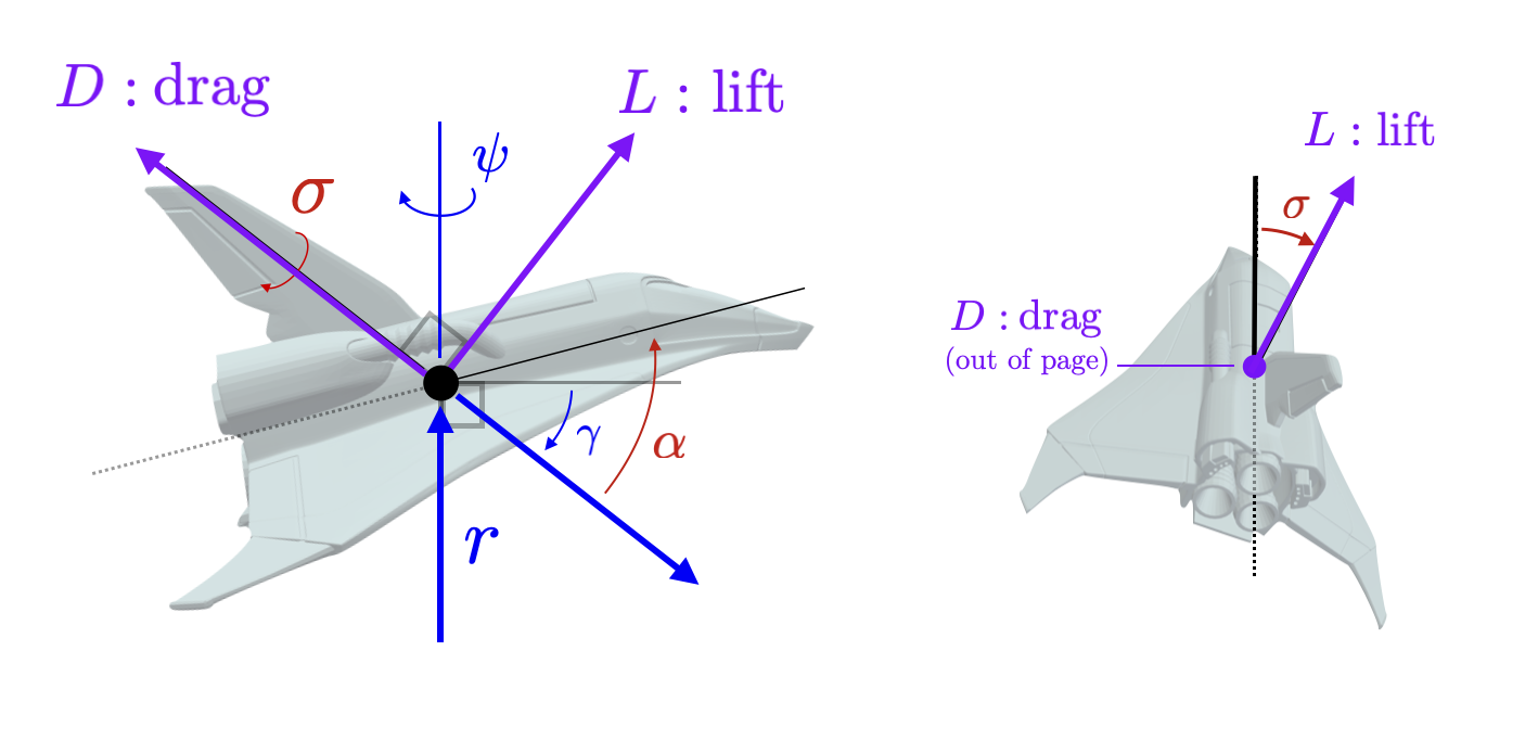
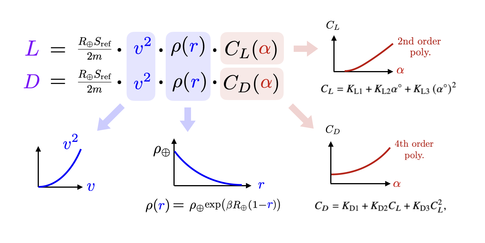
In a glide body hypersonic reentry, these two forces apply the loads that slow down and steer the vehicle. The magnitude of lift and drag is determined by the angle-of-attack, \(\alpha\) via the following two equations. $$ \begin{aligned} L & = \frac{R_\oplus S_\text{ref}}{2m} v^2 \rho(r)C_L(\alpha)\\ D & = \frac{R_\oplus S_\text{ref}}{2m} v^2 \rho(r)C_D(\alpha)\\ \end{aligned} $$ where the density of air is given by \(\rho(r) = \rho_\oplus e^{\beta R_\oplus(1-r)} \) and \(C_L(\alpha)\) and \(C_D(\alpha)\) are the coefficients of lift and drag respectively which are both determined by the bank angle. Each of the terms in these expressions contributes to how lift and drag increase the vehicle speeds up, approaches the earth's surface, and increases it's angle of attack. We break the contributions down in detail in the following figure. From this decomposition we can see that lift and drag forces increase with velocity and with bank angle. The lift and drag forces also increase with air density as \(r\) decreases.
Often to simplify the control problem, the bank angle is restricted to follow a specific profile based on velocity, ie. \(\alpha(v)\) is designed as an increasing function of \(v\). In general, the bank angle is designed to increase with velocity maxing out at a certain level. If we plug in this function \(\alpha(v)\), then we get that lift and drag fixed as function of velocity and radial distance illustrated here.
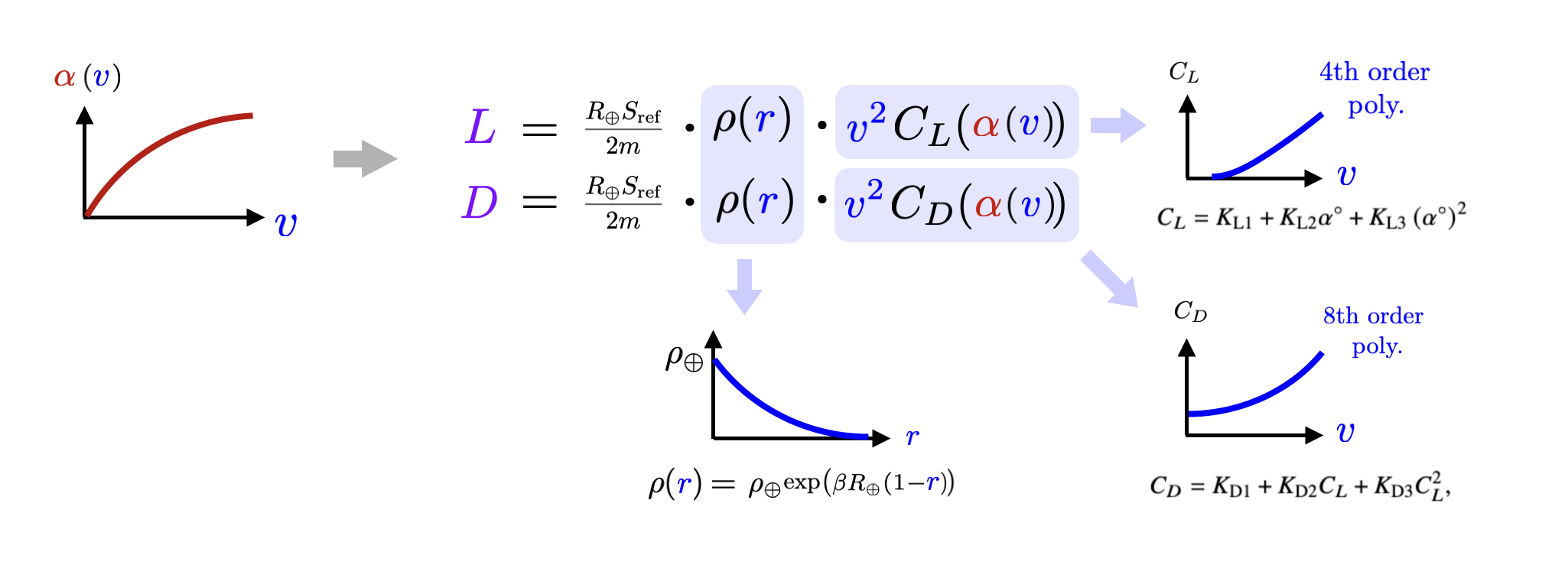
Note that in this case the only control variable is now only the bank angle that allows the vehicle to steer. We will both of these options further on.
DynamicsGiven the above discussion we can present the dynamics. The break up the dynamics into the global position states \((z,\theta,\phi)\) and the local orientation states (\(v,\gamma, \psi \)). The global position states are not affected directly by the control inputs directly but rather only indirectly through the orientation states
$$ \begin{aligned} \begin{bmatrix} \color{blue}{\dot{z}} \\ {\color{blue}\dot{\theta}} \\ {\color{blue}\dot{\phi}} \end{bmatrix} & = \begin{bmatrix} f_r({\color{blue}{z}}) \\ f_\theta({\color{blue}z}) \\ f_\phi({\color{blue}z}) \end{bmatrix} = \begin{bmatrix} {\color{blue}v} \sin {\color{blue}\gamma }\\ \frac{{\color{blue}v} \cos {\color{blue}\gamma} \sin {\color{blue}\psi} }{ {\color{blue}r} \cos {\color{blue}\phi}} \\ \frac{{\color{blue}v} \cos {\color{blue}\gamma} \cos {\color{blue}\psi} }{{\color{blue}r} \cos {\color{blue}\phi}} \end{bmatrix} \end{aligned} $$ These dynamics are simply the result of the local velocity vector transformed into polar coordinates. We illustrate this in the following figure.
The dynamics of the local orientation states are more complicated $$ \begin{aligned} \begin{bmatrix} {\color{blue}\dot{v}} \\ {\color{blue}\dot{\gamma}} \\ {\color{blue}\dot{\psi}} \end{bmatrix} & = \begin{bmatrix} f_v({\color{blue}z}) \\ f_\gamma({\color{blue}z}) \\ f_\psi({\color{blue}z}) \end{bmatrix} + \begin{bmatrix} 0 & -1 \\ \frac{\cos {\color{red}\sigma}}{{\color{blue} v}} & 0 \\ \frac{\sin {\color{red}\sigma}}{{\color{blue}v}\cos{\color{blue}\gamma}} & 0 \end{bmatrix} \begin{bmatrix} {\color{BlueViolet} L} \big({\color{blue}r},{\color{blue}v},{\color{red}\alpha}\big) \\ {\color{BlueViolet} D} \big({\color{blue}r},{\color{blue}v},{\color{red}\alpha}\big) \end{bmatrix} \\ & = \begin{bmatrix} f_v({\color{blue}z}) \\ f_\gamma({\color{blue}z}) \\ f_\psi({\color{blue}z}) \end{bmatrix} + \left(\tfrac{R_\oplus S_\text{ref}}{2m}\right) {\color{blue}v}\rho({\color{blue}r}) \begin{bmatrix} 0 & -{\color{blue}v} \\ \cos {\color{red}\sigma} & 0 \\ \frac{1}{\cos{\color{blue}\gamma}}\sin {\color{red}\sigma} & 0 \end{bmatrix} \begin{bmatrix} {\color{BlueViolet} C_L} \big({\color{red}\alpha}\big) \\ {\color{BlueViolet} C_D} \big({\color{red}\alpha}\big) \end{bmatrix} \end{aligned} $$ with $$ \begin{aligned} f_v({\color{blue}z}) & = - \left(\frac{\sin {\color{blue}\gamma}}{{\color{blue}r}^2}\right) + \Omega^2{\color{blue}r}\cos {\color{blue}\phi}\Big(\sin {\color{blue}\gamma}\cos{\color{blue}\phi} - \cos{\color{blue}\gamma}\sin{\color{blue}\phi}\Big) \\ f_\gamma({\color{blue}z}) & = \frac{1}{{\color{blue}v}}\left({\color{blue}v}^2-\frac{1}{{\color{blue}r}}\right) \left(\frac{\cos{\color{blue}\gamma}}{{\color{blue}r}}\right) + 2 \Omega \cos {\color{blue}\phi} \sin {\color{blue}\psi} \\ & \qquad + \frac{{\color{blue}r}}{{\color{blue}v}}\Omega^2 \cos {\color{blue}\phi} \Big(\cos {\color{blue}\gamma} \cos {\color{blue}\phi} + \sin {\color{blue}\gamma} \cos {\color{blue}\psi} \sin {\color{blue}\phi} \Big) \\ f_\psi({\color{blue}z}) & = \frac{{\color{blue}v}}{{\color{blue}r}}\cos {\color{blue}\gamma} \sin {\color{blue}\psi} \tan {\color{blue}\phi} - 2 \Omega\Big(\tan {\color{blue}\gamma} \cos {\color{blue}\psi} \cos {\color{blue}\phi} - \sin {\color{blue}\phi} \Big) \\ & \qquad + \frac{\Omega^2 {\color{blue}r}}{{\color{blue}v} \cos {\color{blue}\gamma}} \Big(\sin {\color{blue}\psi}\sin {\color{blue}\phi} \cos {\color{blue}\phi}\Big) \end{aligned} $$ Note that these dynamics are control affine in the lift and drag forces and thus in the bank angle \(\alpha\). The bank angle determines the orientation of how the lift force modifies the flight path angle \(\gamma\) and heading angle \(\psi\).
ConstraintsThe constraints are given by
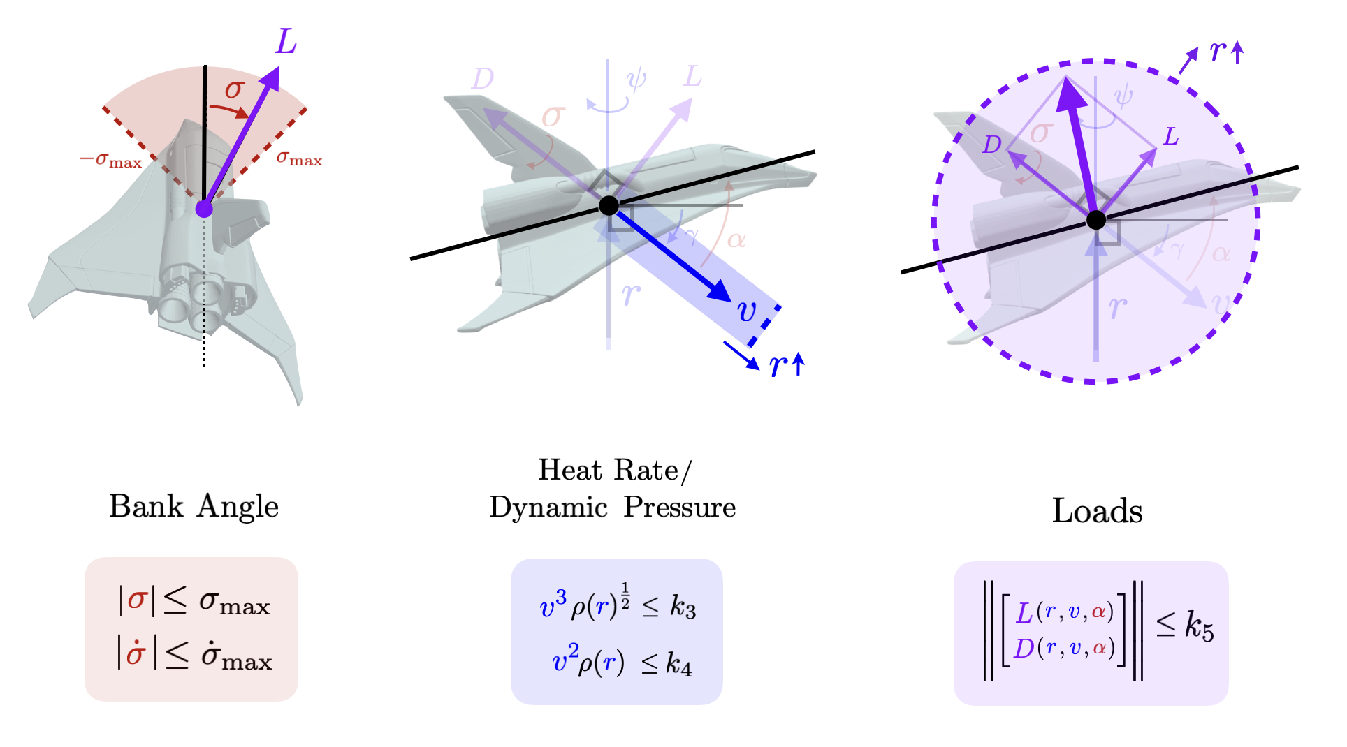
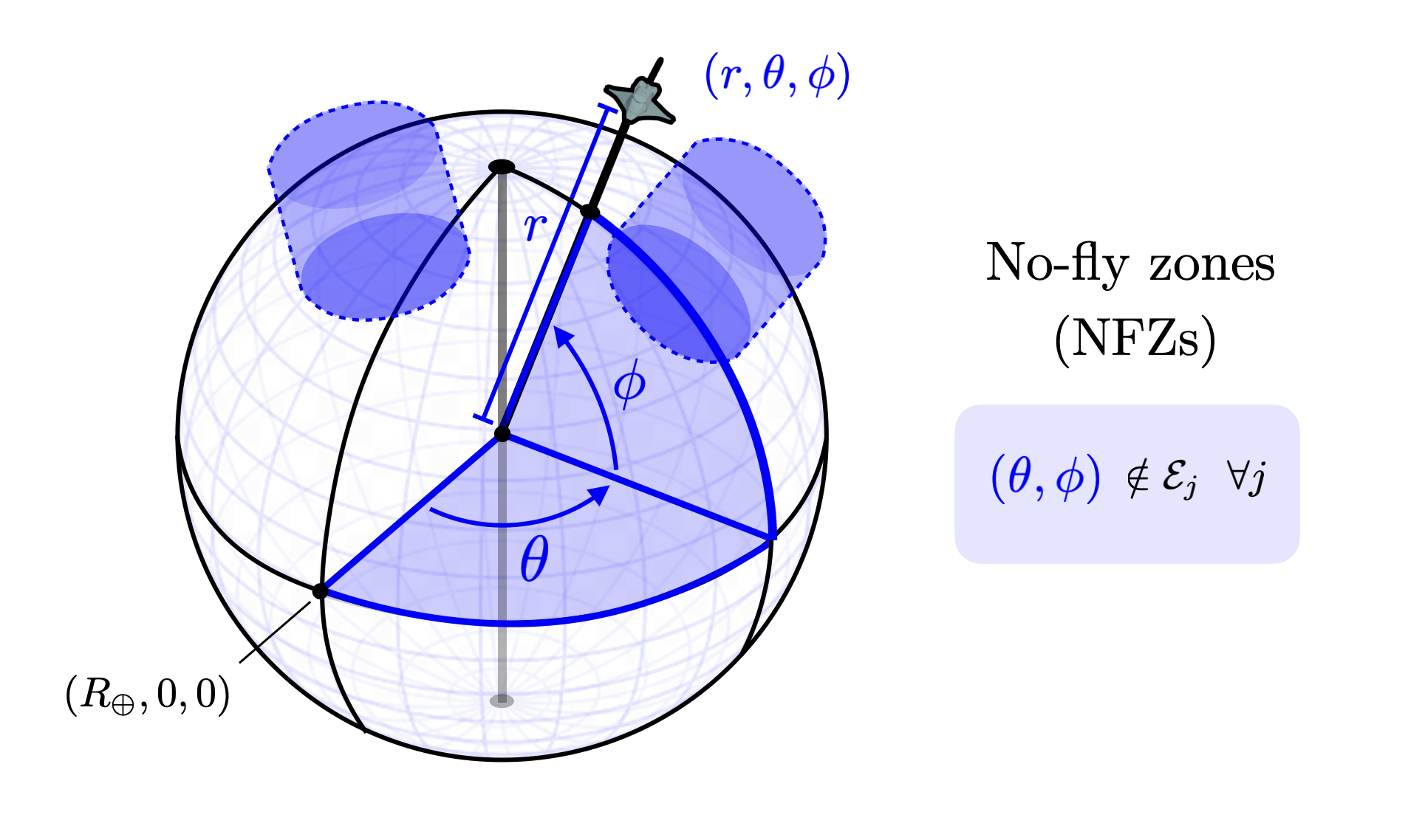
We can also define no fly zone (NFZ) constraints.
